5.6 SELECTION OF THE PRESSURIZATION SYSTEM
At the beginning of the design of a pressurization system, a preliminary study of the various design approaches is conducted. This will provide a technical basis for systems selection, but can become a relatively complex task in view of the great number of tank pressurization techniques developed. In the course of the study, all information pertinent to the wide range of systems is gathered. A standard vehicle configuration and uniform assumptions for mission and performance, structural materials, and other factors affecting the pressurization system design are adopted to permit valid weight and size comparisons of the various systems studied.
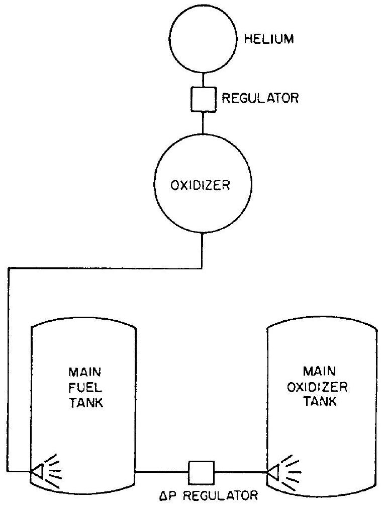
 Figure 5-18.-Main propellant tank series direct injection system.
The four principal selection criteria are: vehicle mission requirements, propellant and material compatibility, system reliability, and system performance. Mission requirements include storability, system instant start and restart, and closely controllable pressure levels (constant or variable). Compatibility includes chemical inertness, freedom from excessively condensible and soluble gas products, and proper pressurant temperature level. Reliability is evaluated on the basis of system complexity, number of failure modes, and number of system components the reliability level of which must be attained economically within the limits of development time and funds allotted. Components which can be expected to require considerable development effort toward satisfactory reliability levels include gas generator assemblies, thrust chamber heat exchangers, large highpressure storage vessels, and hot-gas ducting and regulators. System performance is determined entirely on the basis of gross pressurization system weight which is influenced by
Table 5-1.-Comparisons of Various Tank Pressurization Systems for the A-4 Stage Propulsion System
| System | Stored gas and generants | Gas produced | Total quantity of system components | Number of complex component designs | System overall weight, percent | System overall volume, percent |
|---|---|---|---|---|---|---|
| Helium with thrust chamber heating (fig. 5-2) | Helium | Helium at average | 11 | 3 | 100 | 100 |
| Helium-no heating (fig. 5-1) | Helium | Helium at average | 9 | 2 | 182 | 183 |
| Helium cascade (fig. 5-3) | Helium | Helium at average | 17 | 7 | 81 | 75 |
| Solid propellant gas generator heating helium (fig. 5-12) | Helium, ammonium nitrate base grain | Mixed helium and solid propellant products at average | 15 | 4 | 79 | 72 |
| Solid propellant gas generator with solid subliming coolant (fig. 5-10) | Ammonium nitrate base grain, oxalic acid pellets | Solid propellant products at | 9 | 3 | 53 | 12 |
| Solid propellant gas generator with azide cooling (fig. 5-11) | Viton azide propellant. lithium azide coolant | Nitrogen at | 11 | 4 | 70 | 11 |
| Single liquid propellant gas generator-helium (fig. 5-14) | Helium. hydrazine | Helium at on oxidizer, hydrazine products at on fuel | 11 | 4 | 63 | 51 |
| Dual liquid propellant gas generator with injection cooling (fig. 5-15) | Helium, nitrogen tetroxide, ammonia | Ammonia-rich gas generator products at on fuel; -rich gas generator products at on oxidizer | 16 | 6 | 48 | 16 |
[^5]pressurant molecular weight and specific system weight. The gross weight of the pressurization system is treated as inert weight, since the entire pressurant and system components are part of the vehicle system weight at burnout.
A sample preliminary design study was conducted for the tank pressurization system for the A-4 stage propulsion system. The vehicle mission was assumed to require single-start, constant-thrust, full-duration operations. Eight different pressurization systems were compared.
The results presented in table 5-1, "Total Quantity of System Components" include components of like design; i.e., two identical storage vessels or check valves are considered a quantity of two. "Complex Component Designs" refers to parts requiring relatively long development time and high production cost. Instead of absolute values for overall weight and volume of the various systems, percentages of the selected system (stored helium with thrust chamber heating) are used for comparison.
Design of Turbopump Propellant-Feed Systems
In high-thrust, long-duration liquid propellant rocket engine applications, turbopump feed systems, as shown in figures 1-13, 2-10, 3-3, and 4-58, generally result in lower systems weight and higher performance when compared to pressurized gas feed systems. Turbopump feed systems require only relatively low pump-inlet pressures, and thus propellant-tank pressures, while the major portion of the pressure required at the thrust chamber inlets is supplied by the pumps. This saves considerable tank weight, particularly in large vehicles.
As the overall trend toward higher chamber pressure of liquid propellant rocket engines continues, the role of turbopumps in an engine system becomes of even greater importance, particu-
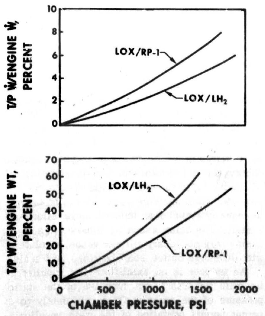
 Figure 6-1.-Variation of turbopump/engine weight and flow ratios with change of chamber pressure.
larly with the intoduction of bigh-performance hydrogen-fueled engines. As shown in figure 6-1 for two propellant combinations, the proportional turbopump-assembly weight in an engine system rises with increasing chamber pressure, as does the required turbopump power expressed as a percentage of total engine propellant flow rate.
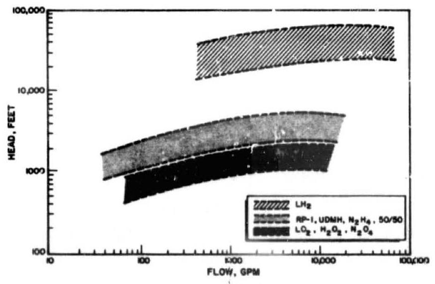
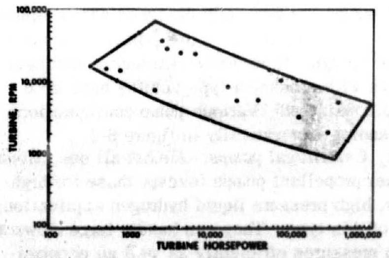
A representative range of pump operating parameters for various liquid propellant rocket engine applications is shown in figure 6-2. Figure 6-3 depicts an envelope of turbine power requirements for a number of actual turbine designs.
 Figure 6-2.-Range of operation for typical propellant pumps.
 Figure 6-3.-Envelope of rocket engine turbine designs.